
Mason Industries - Spring Mounts
Mason Industries is known throughout our industry as one of the pioneers of the Vibration Isolation market. Through relentless product testing and development we are able to provide a reliable and time tested product that is backed by the Mason Industries brand.
Our Engineering department will work tirelessly to provide signed and sealed calculations along with layout drawings and specifications for any of your projects.
We offer our thanks to every contractor and manufacturer who forms our customer base. We believe they favor us because of the practicality of our designs and lower installed cost when product works the first time. We stand behind what we sell as no other competitor. We thank our whole representative organization for their hard work, professionalism, integrity and loyalty. We look forward to serving you. Diversified Fluid Controls is proud to be the exclusive representative for Mason Industries here in South Florida.
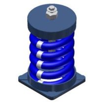
Unhoused Spring Mounts
Models: SLF, SLFH
Spring isolators shall be free standing and laterally stable without any housing and complete with a molded neoprene cup or 1/4” (6mm) neoprene acoustical friction pad between the baseplate and the support. All mountings shall have leveling bolts that must be rigidly bolted to the equipment. Installed and operating heights shall be equal. The ratio of the spring diameter divided by the compressed spring height shall be no less than 0.8. Springs shall have a minimum additional travel to solid equal to 50% of the rated deflection. Submittals shall include spring diameters, deflection, compressed spring height and solid spring height. Mountings shall be type SLF as manufactured by Mason Industries, Inc.
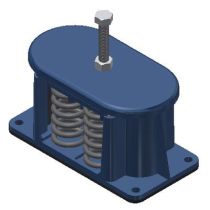
Housed Spring Mounts
Models: C, CI, CIP, CIW
TYPE “C” Spring Mountings provide a packaged solution to troublesome vibration problems. Since the static deflection of the spring element is much greater than that provided by most rubber materials, these units will perform where it is necessary to establish low natural frequencies or to use a mounting that is more yielding than the supporting floor. Type “C” mountings are specifically designed for noise and vibration free application in critical areas on light concrete or wooden floors.
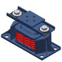
Restrained Spring Mounts
Models: SLR, SLRW, SLRSO, SLRSOW, SLRSOEBP, SLRS, SLRSW, SLRSEBP, SLRJ, SLRJW
Restrained spring mountings shall have an SLF mounting as described in SLF Specification, within a rigid housing that includes vertical limit stops to prevent spring extension when weight is removed. The housing shall serve as blocking during erection. Installed and operating heights are equal. Restraining Bolts shall have a neoprene bushing between the bolt and the housing. A clearance of 1/4” (6mm) shall be maintained around restraining bolts and the bushing so as not to interfere with the spring action. Limit stops shall be out of contact during normal operation. Since housings will be bolted or welded in position there must be an internal isolation pad. Housing shall be designed to resist all seismic forces. Mountings shall have an OPA pre-approval from OSHPD in the state of California certifying the maximum certified horizontal and vertical load ratings. Mountings shall be type SLR or SLRS as manufactured by Mason Industries, Inc. This mount is perfect as a Cooling Tower Spring Mount to withstand Miami-Dade Windload ratings. Ask about our signed and sealed PE calculations for your project.
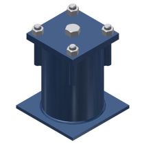
Accessible Spring Mounts
Models: KI, KIJ
To complete an envelope, secondary walls must be introduced with the same consideration given to mass and air gap as covered in the floor discussion. The problem is simpler, because the walls normally support only their own weight and they need not have the structural strength of the floor. Poured concrete or concrete block walls should approach the floor density. It is most important that block joints are properly filled with mortar and painting the walls so the construction is more nearly airtight helps. The best approach is resting these walls on the perimeter of the floating floor so the floor isolation system serves the walls as well. If this is not possible, the second choice is supporting the isolated wall on the structural slab with continuous LDS pads, and providing a caulked fiberglass seal between the floating floor and the wall as described for the perimeter in the previous specifications.
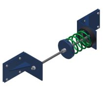
Thrust Restraints
Models: WBI, WBD
The horizontal thrust restraint shall consist of a spring element in series with a neoprene molded cup as described in specification 5 with the same deflection as specified for the mountings or hangers. The spring element shall be designed so it can be preset for thrust at the factory and adjusted in the field to allow for a maximum of 1/4” (6mm) movement at start and stop. The assembly shall be furnished with 1 rod and angle brackets for attachment to both the equipment and the ductwork or the equipment and the structure. Horizontal restraints shall be attached at the centerline of thrust and symmetrical on either side of the unit. Horizontal thrust restraints shall be type WBI/WBD as manufactured by Mason Industries, Inc.
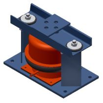
Air Spring Mounts
Models: MAS, SLR-MAS, SSLR-MAS, SLRW-MAS, 451AS, MT, SLR-MT, SSLR-MT, SLRW-MT
Air Springs shall be manufactured with upper and lower steel sections connected by a replaceable flexible nylon reinforced neoprene element. Air spring configuration shall be multiple bellows to achieve a maximum natural frequency of 3 Hz. Air Springs shall be designed for a burst pressure that is a minimum of three times the published maximum operating pressure. All air spring systems shall be connected to either the building control air or a supplementary air supply and equipped with three leveling valves to maintain leveling within plus or minus 1/8” (3mm). Submittals shall include natural frequency, load and damping tests performed by an independent lab or acoustician. Air Springs shall be type MT and leveling valves type LV as manufactured by Mason Industries, Inc.