Taco LoFlo System

Features:
- All-in-one injection circulator, zone circulator and common bridge piping
- Built-in hydraulic separator
- Only 4 piping connections
- Greatly reduces installation time
- Substantial space savings
- Maintenance free, wet rotor injection and zone circulators
- Replaceable cartridge
- Integral flow check
- Variable speed drive injection and optional
- Choose from a variety of sizes and capacities for the injection and zone circulator

The award-winning TACO LOFlo system sets a new standard in comfort, ease of design, and Green Building energy performance for small to large buildings.
Introduction
Designers know that the demand for super efficient comfort systems grows each day. The industry has responded with a variety of new “Green” hydronic products and system concepts that yield dramatic benefits over the traditional and conventional airside designs of the past. The award-winning Taco LOFlo® Mixing Block (LMB) is one such product that sets a new standard for comfort, ease of design, and superior energy performance in small to large buildings. The LOFlo Mixing Block can easily be incorporated into heating and cooling systems for cost-effective results in a variety of areas. When employed in conjunction with Taco’s latest system approaches, outstanding benefits accrue to designers, installers, owners, and users alike
The LOFlo® Concept
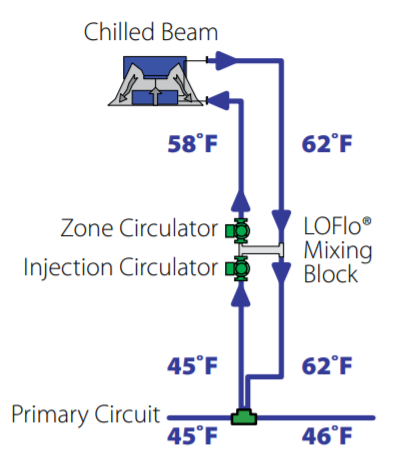
The LMB is a complete injection mixing station contained in a simple factory-assembled package that controls each individual zone at the lowest possible flow rate by maintaining the highest possible supply water temperatures in cooling and lowest possible supply water temperatures in heating. The LMB consists of a single cast header that functions as a hydraulic separator to which small circulators are attached – one for the primary system flow and the other an injection circulator that adjusts to precisely match the required load on a given zone. When installed within modern radiant systems ( wall, floor, or ceiling panels) or chilled beam systems (active or passive), only 2 pipes are needed. Flow rates are reduced since there are no control valves, balancing valves, or piping losses to overcome. The small, reliable circulators take the place of all of these components. The LMB automatically provides only the flow and temperature of water needed to satisfy the zone load at any given time.
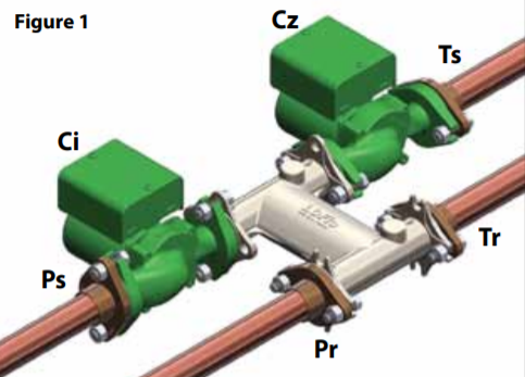
Figure 1 illustrates how the water supply from the primary circuit enters the LMB at Port (Ps). The return water from the secondary terminal loop enters the LMB at terminal (Tr). As the terminal unit calls for either heating or cooling, the Injection Circulator (Ci) varies in speed / flow to blend the two water temperatures to satisfy the needs of the zone. This blended supply water is sent to the terminal though Port (Ts) and primary return water exits the LMB at Port (Pr). A variety of sizes of LOFlo mixing blocks can handle flows up to 30 gpm, making them suitable for almost all installations.

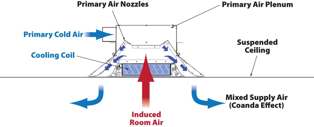
Figure 8 - Active Chilled Beam

Application: Active Chilled Beams
Active Chilled Beams To further increase a chilled beam’s cooling capacity, conditioned ventilation air from the DOAS can be used to flow air through a chilled coil, further increasing the beam’s convective component by using forced convection. This configuration is referred to as an “active chilled beam” as shown in Figure 8.
Ventilation air from the DOAS is introduced to a chilled beam into a plenum above the coil and through a venturi, generating a higher velocity and, subsequently, a lowerpressure region inside the lower plenum in the chilled beam. This low-pressure region induces room air to flow through the chilled coil and mix with primary air from the DOAS. The airflow over the chilled coil is reversed for an active chilled beam, and the induced room air flows up through the coil.
Active chilled beams are sometimes referred to as “induction diffusers.” They are really 1970’s induction unit technology, only mounted in a ceiling and supplied with high temperature chilled water.
Air from an active chilled beam is introduced into a space through a slot diffuser, creating a Coanda effect. This eliminates drafts by preventing the chilled beam from “dumping” cold air. The Coanda effect is the ability of a cold air stream to hug the ceiling and not dump. This is the case because the air is discharged at higher velocity by the slot diffuser creating an upward force from the static pressure difference between the air stream and the room (Bernoulli’s Principle). This forces the cold air to hug the ceiling and not dump.
Inducing warm room air to blow through a chilled coil substantially increases chilled-beam capacity. Active-chilled-beam capacities range from 400 to 600 Btuh per square foot of beam or beam-coil area. Depending on the temperature and quantity of primary supply air from a DOAS, this can add an additional 300 to 400 Btuh per square foot of beam or beam-coil area. An active chilled beam can therefore deliver from 700 to 1000 Btuh per square foot of beam or beam-coil area between the chilled coil and primary air.
Interested in learning about Active Chilled Beams in Miami?
We have successfully installed the Taco LoFlo System with Active Chilled Beams in three separate projects with over 400 individual chilled beams, and over 30 zones in Miami, FL. Let us help you design your next LoFlo project.